Material Graph Editor
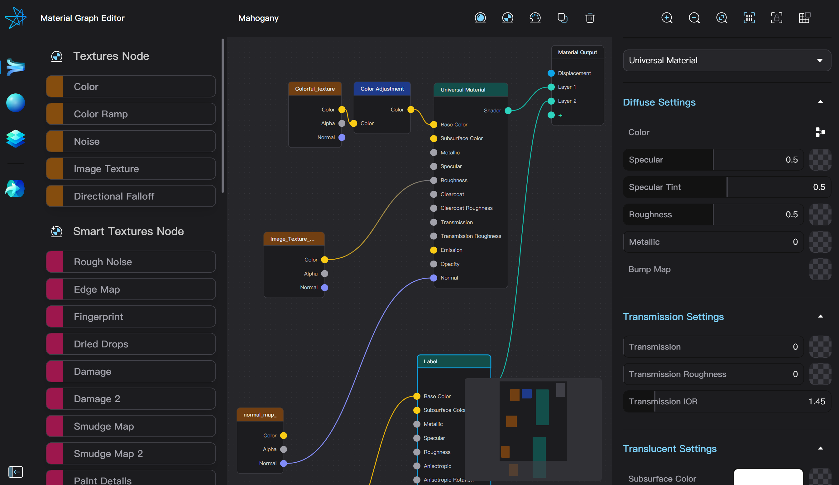
Clicking the "Material Graph Editor" button in the settings of a Node Material opens the Taitopia Material Graph Editor. The interface of the Material Graph Editor is divided into four parts: the top toolbar, the asset library on the left sidebar, the graph canvas, and the parameter panel on the right sidebar.
Basic Node Operations
Graph Canvas
- Clicking on a node selects it.
- Dragging from an empty area allows selection of multiple nodes.
- Dragging on a node moves it. The Material Output node can only be selected, not moved.
- **Dragging with the middle or right mouse button **moves the current view of the canvas.
- Scrolling with the mouse wheel zooms in or out the view.
- Double-clicking on an empty area zooms the view of the canvas to the double-clicked location.
- The mini-map in the lower right corner of the canvas shows the whole node graph. Dragging directly on the mini-map also changes the view of the canvas.
Adding a Node
Nodes can be added in the node editor using the following methods:
- Click the "Add Plastic Material Node," "Add Image Texture Node," or "Add Color Adjustment Node" buttons in the toolbar.
- Use the asset library on the left sidebar to add nodes, textures, or materials.
- Right-click in the blank area of the node operation area and add nodes from the context menu.
Renaming Materials and Nodes
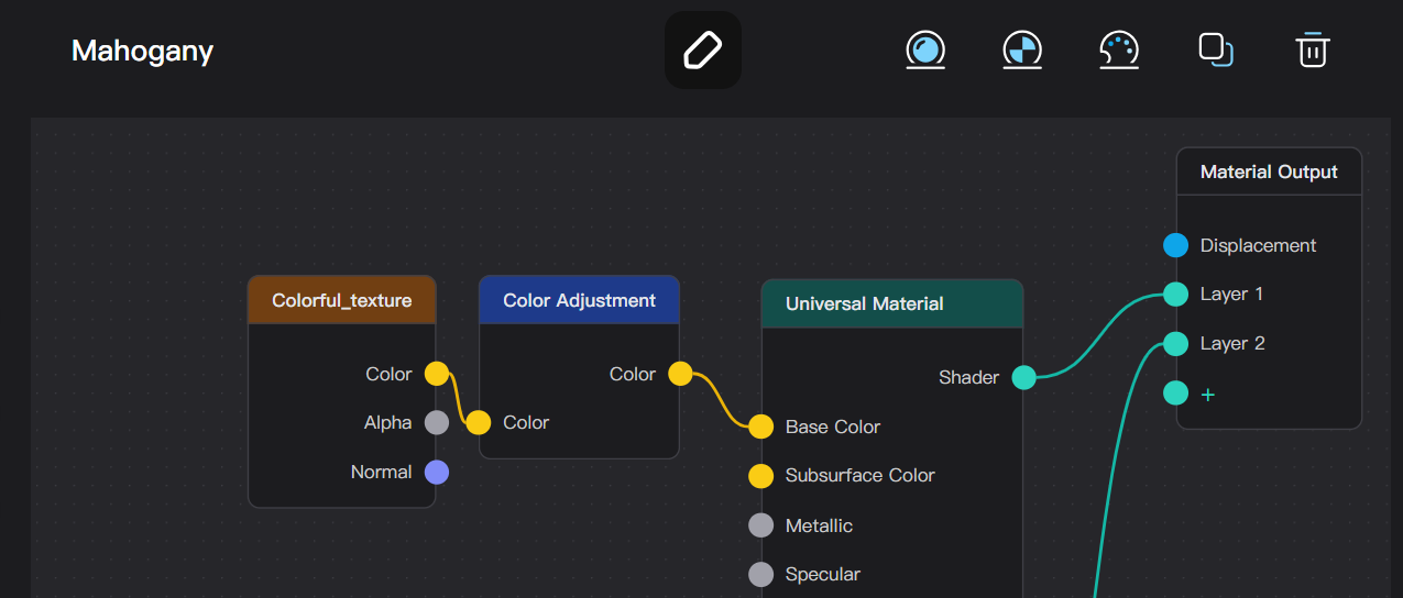
- Hovering the mouse over the material name on the left side of the toolbar reveals the rename button. Clicking this button allows you to change the name of the material.
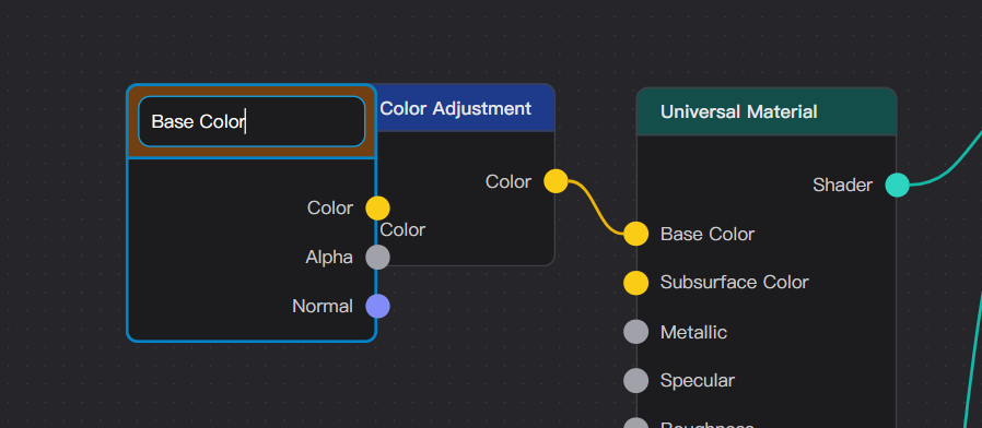
- Double-clicking the name of a node or right-clicking and selecting "Rename Node" from the node menu allows you to change the name of a node.
Connecting Nodes
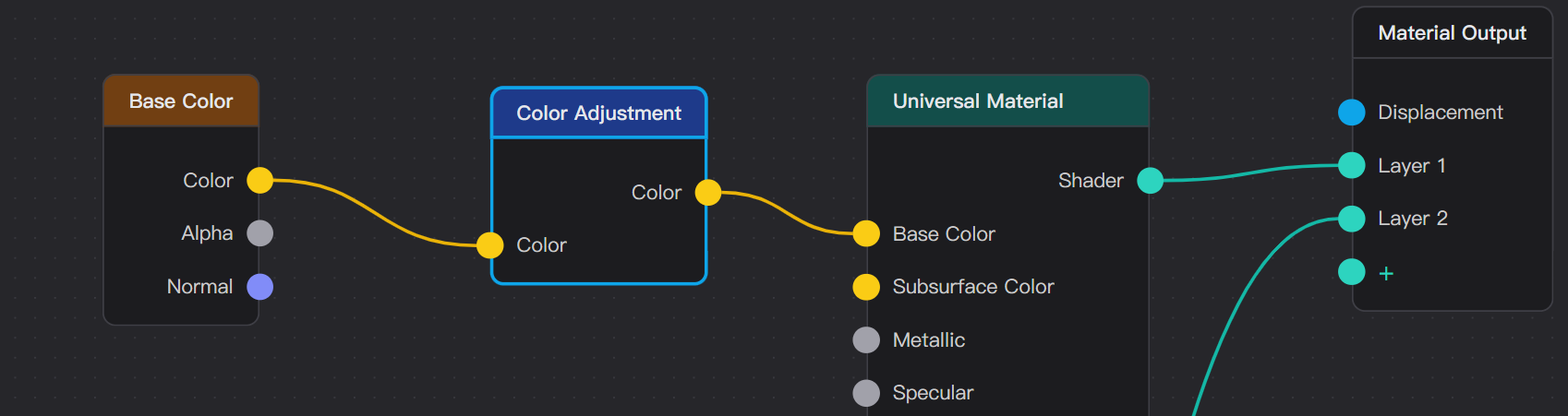
Each node has several input sockets and output sockets, represented by circles on the left and right sides of the node. Input sockets are on the right, and output sockets are on the left.
In Taitopia, nodes have the following types of sockets:
- RGB Color (yellow), representing color textures, such as the color output of an Image Texture node and the base color input of a Universal Material node.
- Grayscale (gray), representing grayscale textures, like the opacity of an Image Texture node and the roughness of a Universal Material node.
- Normal (purple), representing normal map textures.
- Shader/Material (cyan), representing rendered material layers. Each layer in a Node Material corresponds to a shader/material type input that can be connected.
- Geometry (blue), representing changes to object geometry through images or other textures. Currently, Taitopia only supports displacement maps as this type of output.
Dragging from an input socket to an output socket or vice versa adds an edge to the node graph. An output socket can connect to multiple edges, but an input socket can only connect to one edge.
Only sockets of the same or compatible types can be connected. RGB Color and Grayscale sockets are compatible with each other.
Tip – Connecting Normal Type sockets
Currently in the material graph, the normal type is compatible with RGB Color and Grayscale as their internal data types can be converted between each other. If you fully understand how normal maps work, you may use nodes that operate on RGB colors to adjust normal maps. However, we do not recommend connecting normal sockets with any other types in general, as this will very likely lead to incorrect normal map effects.
Previewing Nodes
When the material graph is complex, you can use the Preview Node feature to view the output of each node separately, which is helpful for adjusting material effects. Selecting a node and pressing the keyboard shortcut C or choosing "Preview Node" from the right-click menu enters the node preview mode.
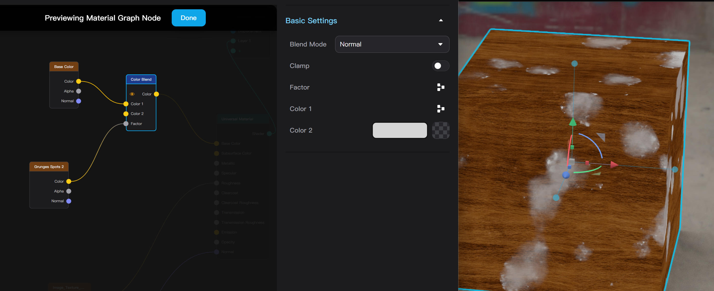
After entering the preview mode, you can click to select an output socket, and the 3D viewport will directly render the result from the output of this socket.
All selectable nodes are highlighted in the preview mode. If the node being previewed is connected to other incoming nodes, you can preview the output of an incoming node without exiting preview. However, you need to exit and re-enter preview mode to preview nodes outside the current highlighted range.
In the preview mode, you can change the parameters of any highlighted node, and the results will be updated in real-time in the 3D viewport. However, you cannot change edit edges or add/delete nodes in the preview mode.
Clicking the "Done" button at the top, pressing the Esc key, or pressing C again exits preview mode.
Graph Editor Toolbar
The top toolbar of the Material Graph editor includes a series of buttons for quick actions:
- "Add Plastic Material Node": Adds a plastic material node at a random location in the node operation area.
- "Add Image Texture Node": Adds an image texture node at a random location in the node operation area.
- "Add Color Adjustment Node": If the currently selected node has a color output, a color adjustment node connected to the color output is added. If the color output is already connected, the color adjustment node will be inserted into this line. If the selected node does not have a color output or no node is selected, a color adjustment node is added at a random location.
- "Duplicate Selected Node": Clones a selected node or multiple nodes. The same as the "Duplicate" option in the right-click menu and the shortcut Ctrl/Cmd + D.
- "Delete Selected Node and Edge": Deletes a selected node or multiple nodes. The same as the "Delete" option in the right-click menu and the shortcut Delete/Backspace.
- "Zoom In": Zooms in the view of the graph canvas.
- "Zoom Out": Zooms out the view of the graph canvas.
- "Aim View at Current Graph": Moves the view range of the graph canvas to include all nodes in the current node graph.
- "Arrange Nodes": Organizes the positions of all nodes in the current node graph so they align.
- "Lock/Unlock Nodes": When locked, nodes cannot be selected and only the view of the graph canvas can be moved.
- "Snap to Grid On/Off": When snapping turned on, moving nodes will automatically snap to the grid points in the canvas.
Graph Editor Asset Library
The left sidebar of the Material Graph Editor is the asset library, including the node library, official texture library, official material library, and personal asset library.
Click the “Collapse Menu” button on the bottom left to hide the left sidebar.
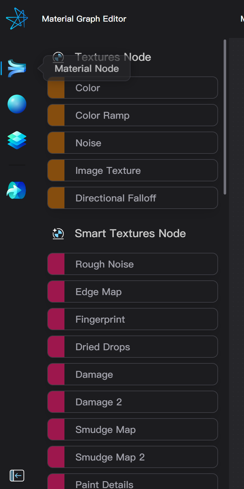
Node Types
Nodes in the node library are categorized by type. Clicking on a node or dragging it into the canvas adds a node of the given type. Taitopia’s material nodes are categorized as follows, with each category of nodes distinguished by the color of the title bar in the Material Graph Editor:
- Texture Nodes (orange): Generate basic texture patterns, including solid colors, gradients, image, noise, etc.
- Smart Texture Nodes (red): Generate resolution-independent procedural textures, such as edge wear, stains, paint details, etc. The node library provides some commonly used smart textures, whereas a more comprehensive collection of smart textures can be found in the "Smart Textures" category of the official texture library.
- Material (Shader) Nodes (cyan): Generate rendered material layers. Connecting the "Shader" output of a material node to the "+" socket of the material output node adds a material layer. A node graph can contain up to 5 material layers.
- Geometry Nodes (green): Change geometry of the model through textures. Currently, the geometry nodes category only contains the Displacement node so it is put into the same sections as material nodes.
- Adjustment Nodes (blue): Adjust and blend texture maps, such as color adjustment, color blending, bump to normal, and normal blending.
Please note that the "Height" input of the displacement node can only be connected to an image texture node. This means that Taitopia currently only supports using images as displacement maps and does not support smart textures or other procedural textures like gradients and noise.
Using Texture and Material Libraries
In the material graph editor, you can also use official and personal asset libraries for materials and textures.
Clicking a material in the material library or dragging a material into the node operation area adds all the nodes of that material to the current graph. If the material from the library is a Basic Material, it will be automatically converted to a Node Material.
Clicking a texture in the texture library or dragging a texture into the node operation area adds the corresponding node for the texture or smart texture to the current node graph. The node editor does not support uploading textures to the personal asset library.
Node Parameter Panel
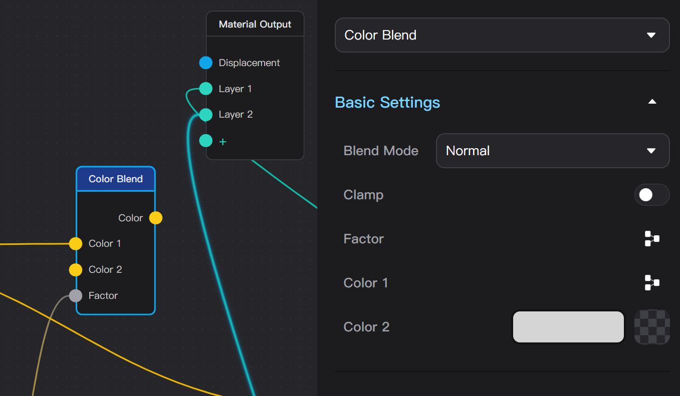
Changing Node Parameters
Selecting a node in the material graph displays the node's type and all adjustable parameters in the right sidebar of the node editor.
You can switch the type of a node in the parameter panel. After switching, the same input/output sockets and parameters as before the switch are retained, and new parameters are reset to default values.
The parameter panel of a material node contains the same content as the main editor window when a material layer is selected. You can also add textures directly from the material node's parameter list.
Material Output Node
Selecting the material output node allows setting the material's round corner rendering and editing material layers. In the material layer list of the Material Graph Editor, you can add, sort, and delete layers, but selecting a layer does not reveal the corresponding material parameters of a layer.